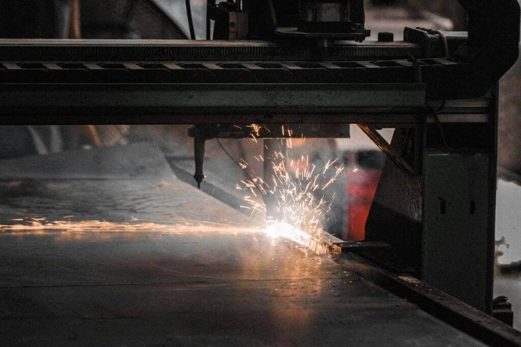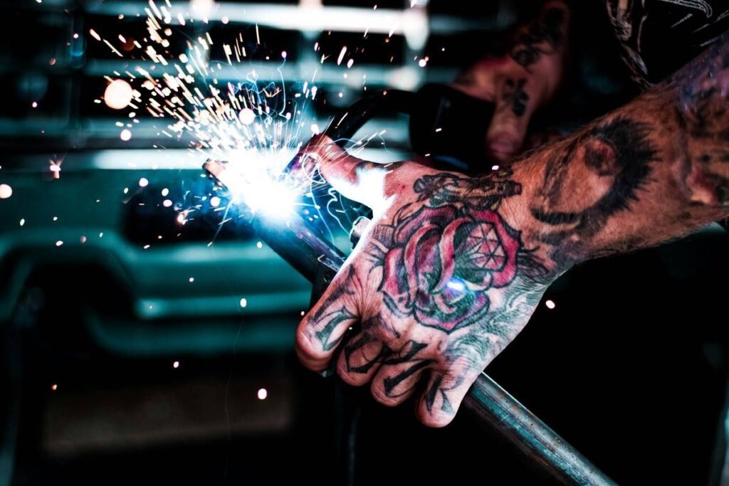
Most shops waste hours—and material—trying to force outdated plasma cutting techniques onto complex jobs. The result? Inconsistent bevels, wasted consumables, and margins that evaporate faster than molten metal. But there’s a smarter path. Precise plasma modeling methods and applications can slash cycle time, boost accuracy, and turn your cutter into a profit engine—not just a torch.
Why Traditional Plasma Cutting Fails on Complex Geometry
Legacy systems treat every cut like it’s straight steel on a flat table. Real-world work isn’t like that. Curved brackets, tapered ducts, angled brackets—they demand dynamic control. And generic CNC paths ignore arc physics. The plasma arc doesn’t move like a laser beam—it lags, flares, and reacts to voltage shifts in milliseconds.
So you get dross buildup on tight radii. Kerf width varies mid-cut. Edge squareness? Forget it on anything over 1-inch thick. These aren’t operator errors—they’re modeling gaps baked into the software.
Plasma Modeling Methods and Applications: A Step-by-Step Precision Framework
Forget “set it and forget it.” True modeling starts before spark meets steel. It requires simulating the arc’s thermal behavior under real load—not just copying CAD lines.
Thermal Path Simulation
Advanced controllers now model heat diffusion across the workpiece in real time. This adjusts feed rate dynamically—not just at corners, but during long straight runs where plate temperature rises invisibly. You avoid warping without slowing down unnecessarily.
Voltage Feedback Loop Integration
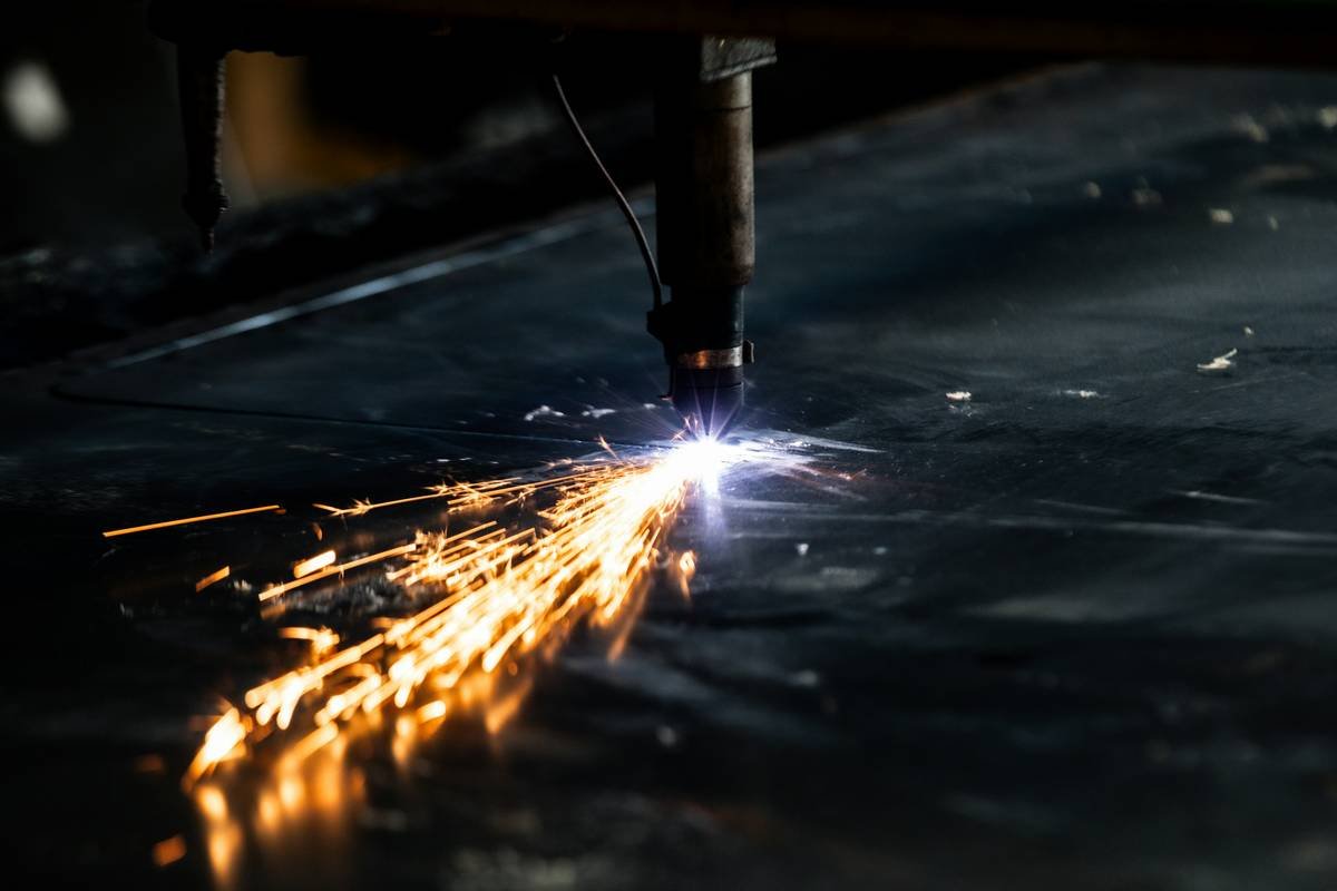
Plasma arc voltage correlates directly with cut height. Instead of guessing standoff distance, closed-loop systems read voltage fluctuations 10,000 times per second and tweak torch height instantly. No more burnt tips from accidental contact.
Gas Mix & Amperage Profiling
Not all cuts need max power. For thin stainless or aluminum, lower amperage with nitrogen-hydrogen mix reduces oxidation and improves edge smoothness. Modeling this per-material eliminates post-grinding on finish-critical parts.
| Modeling Method | Best For | Cost Impact | Accuracy Gain vs. Standard |
|---|---|---|---|
| Static G-Code (Legacy) | Simple straight cuts on mild steel | Low upfront, high waste | Baseline |
| Thermal-Aware Pathing | Complex contours, multi-thickness assemblies | +15% software cost, -30% scrap | ±0.005” edge tolerance |
| Real-Time Arc Voltage Control | Beveled edges, stacked cutting | +22% hardware integration | 40% better bevel consistency |
| Material-Specific Gas Profiling | Stainless, aluminum, non-ferrous | +8% gas system upgrade | Near-laser edge quality |
The Industry Secret: Most Shops Over-Cut by Design
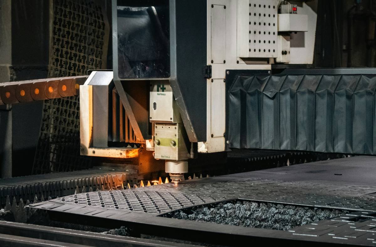
Here’s what suppliers won’t tell you: plasma cutters are often run too hot to compensate for poor modeling. Why? Because if the software can’t predict kerf drag, operators crank amperage to “burn through cleanly.” But that melts the top edge, widens the kerf unpredictably, and ruins nest efficiency.
The fix isn’t a bigger power supply—it’s smarter interpolation. One Midwest fabricator switched to adaptive modeling and dropped their average cut current by 18%. Their nozzle life doubled. Part fit-up improved so much they eliminated two grinding stations. All from treating the arc as a physical system—not just a toolpath overlay.
Frequently Asked Questions
What materials can plasma modeling methods handle?
Steel, stainless, aluminum, copper, and even expanded mesh—when paired with correct gas profiles and real-time arc control.
Do I need new hardware for advanced plasma modeling?
Not always. Many retrofits add sensor kits and updated controllers to existing Hypertherm or Lincoln systems. Check I/O compatibility first.
How much faster is modeled plasma vs. standard cutting?
On intricate parts, 22–35% faster due to optimized feed rates and fewer re-cuts. Simpler jobs see minimal speed difference—but far better edge quality.