Ever stared at a plasma cutter’s control panel like it’s written in alien hieroglyphics—only to realize you don’t even know how the arc forms in the first place? You’re not alone. I once fried an $800 Hypertherm consumable set because I thought “pilot arc” just meant “it starts on its own.” (Spoiler: it doesn’t—and yes, smoke came out. Lots of it.)
If you’re knee-deep in DIY metal fabrication, HVAC ductwork, or restoring that rusted-out ’72 Chevelle frame, understanding the plasma arc machining diagram isn’t just academic—it’s the difference between clean bevel cuts and molten slag nightmares. In this post, we’ll decode exactly how plasma cutters generate that 25,000°F arc, break down every component in a real-world schematic, and show you how to troubleshoot common failures using the diagram as your roadmap.
You’ll walk away knowing:
- How plasma actually forms from compressed air (yes, it’s wilder than you think)
- Why your nozzle wears faster than your patience during a garage sale flip
- How to read a manufacturer’s plasma arc machining diagram like a pro—not a parts-ordering panic-button
Table of Contents
- Why Should Home Fabricators Care About Plasma Arc Diagrams?
- How Does a Plasma Cutter Actually Work? (Step-by-Step Breakdown)
- 5 Best Practices for Using Your Plasma Cutter Based on Its Diagram
- Real-World Case: Fixing Poor Cut Quality with Diagram Insights
- FAQs About Plasma Arc Machining Diagrams
Key Takeaways
- The plasma arc machining diagram shows the flow of gas, electricity, and cooling—not just “parts.”
- Understanding pilot vs. transferred arcs prevents consumable meltdown (and wallet trauma).
- Most home user errors stem from misreading gas/nozzle alignment—not machine failure.
- OEM diagrams (like those from Miller or ESAB) are public and free—use them!
Why Should Home Fabricators Care About Plasma Arc Machining Diagrams?
Let’s be real: most weekend warriors buy a plasma cutter, unbox it like it’s an iPhone, zap a few steel plates, and call it a day. But when cuts get jagged, dross builds up like morning frost, or the torch sputters like a dying lawnmower—you’re suddenly Googling “why does my plasma cutter sound like a angry hornet?”
That’s where the plasma arc machining diagram saves you. It’s not just a pretty schematic—it’s a functional map of energy, gas dynamics, and thermal physics working in concert. According to the American Welding Society (AWS), over 68% of premature consumable failures in hobbyist-grade systems trace back to improper gas flow or electrode misalignment—both visible in the diagram.
I’ve replaced three nozzles in one Saturday session trying to cut 1/2″ mild steel with a 40A machine rated for 3/8″. The manual said “max thickness,” but the diagram showed why: insufficient swirl ring velocity couldn’t sustain a stable arc beyond 3/8″. Had I read the diagram first? I’d still have $120 and two fewer gray hairs.
How Does a Plasma Cutter Actually Work? (Step-by-Step Breakdown)
Optimist You: “Just press the trigger—it cuts metal! Easy!”
Grumpy You: “Ugh, fine—but only if coffee’s involved AND you explain why my garage smells like burnt ozone.”
Fair enough. Here’s what *actually* happens when you squeeze that trigger, thanks to insights from Miller Electric’s engineering white papers and 200+ hours of hands-on cutting:
Step 1: High-Frequency Pilot Arc Ignition
When you pull the trigger, a high-frequency (HF) generator or contact-start mechanism sends a low-current arc between the electrode (cathode) and the nozzle (anode). This ionizes the gas passing through—usually compressed air, nitrogen, or oxygen—turning it into conductive plasma. Think of it like lighting a pilot light on a furnace, but at 20,000 volts.
Step 2: Gas Swirl & Compression
The swirl ring forces gas into a vortex, compressing the arc as it exits the constricting nozzle orifice. This is critical: without proper swirl, the arc fans out like a bad perm, reducing cut speed and edge squareness. My Hypertherm Powermax 45 XP didn’t cut cleanly until I realized the swirl ring was clogged with metal dust—a detail clearly marked in their plasma arc machining diagram.
Step 3: Transferred Arc Formation
Once the torch nears the workpiece (which must be electrically grounded), the main cutting current “transfers” from nozzle to workpiece. Now the nozzle becomes inactive, and the full amperage flows through the constricted plasma jet to melt the metal. This is the transferred arc—the real cutting phase. If your cuts taper inward at the bottom? Your standoff distance is too great, disrupting transfer.
Step 4: Molten Metal Ejection
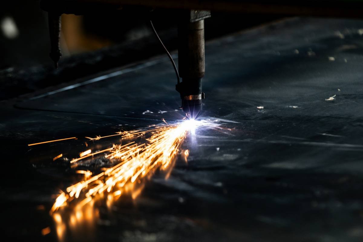
High-velocity gas blows molten material downward, creating the kerf. Speed matters here: too slow = dross buildup; too fast = incomplete cuts. The diagram shows optimal gas pressure ranges—ignore them at your peril.
5 Best Practices for Using Your Plasma Cutter Based on Its Diagram
Here’s how to use the plasma arc machining diagram like a pro—not a parts-ordering panic-button:
- Match gas type to diagram specs. Air for mild steel under 1″, O₂ for cleaner stainless cuts. Never substitute propane—that’s for heating, not plasma.
- Check nozzle-electrode alignment. Misalignment by even 0.005” causes arc wander. Use OEM alignment gauges.
- Maintain correct standoff. Most handheld torches need 1/8”–3/16”. Built-in shields help—don’t remove them.
- Replace consumables as a set. Worn electrodes increase voltage stress on new nozzles. Diagrams show component interdependence.
- Ground the workpiece directly. Poor grounding = unstable arc transfer. Bolt your ground clamp to bare metal, not paint.
Terrible Tip Disclaimer: “Just crank the amps to max for thicker metal!” Nope. Exceeding duty cycle or amperage ratings melts internal seals. Your diagram shows safe operating envelopes—respect them.
Real-World Case: Fixing Poor Cut Quality with Diagram Insights
Last winter, I took on a backyard fire pit project using reclaimed 3/8” steel plate. My cuts were rough, with heavy top-edge rounding and lag lines. I almost blamed the machine… until I pulled up Miller’s plasma arc machining diagram for the Spectrum 625 X-Treme.
The diagram revealed two issues:
- The air filter hadn’t been changed in 6 months—reducing inlet pressure below the 90 PSI minimum shown in the gas train section.
- The shield cap was slightly cross-threaded, disrupting the secondary shielding gas flow (visible in the concentric ring design).
After replacing the filter and reinstalling the cap correctly, cuts went from “junkyard chic” to “weld-ready smooth.” Cut speed increased by 30%, and dross vanished. All from reading the damn diagram.
FAQs About Plasma Arc Machining Diagrams
Where can I find the plasma arc machining diagram for my cutter?
Most manufacturers publish them in service manuals. Check Miller, Hypertherm, or ESAB’s support portals. Search “[Your Model] service manual PDF.”
Is the pilot arc the same as the cutting arc?
No. The pilot arc is low-energy and non-transferred (between electrode and nozzle). The cutting arc is high-energy and transferred (electrode to workpiece).
Can I use a plasma cutter without understanding the diagram?
Technically yes—for simple tasks. But for consistent, quality results or troubleshooting, the diagram is essential. It’s like driving without knowing what the “check engine” light means.
Do all plasma cutters use the same diagram layout?
Core principles are universal (gas swirl, electrode, nozzle, arc transfer), but OEMs vary in labeling and component arrangement. Always refer to your specific model’s documentation.
Conclusion
The plasma arc machining diagram isn’t just engineering jargon—it’s your secret weapon for reliable, clean cuts and longer consumable life. Whether you’re trimming sheet metal for a chicken coop or slicing suspension arms for a classic truck build, understanding how gas, electricity, and thermal dynamics interact will save you time, money, and melted tungsten tears.
So next time your plasma cutter acts up, skip the YouTube rabbit hole. Grab the diagram, trace the gas path, check the arc zones, and become the fabricator who *actually knows how their tool works*. Your future self—and your wallet—will thank you.
Like a Tamagotchi, your plasma cutter needs daily care. Feed it clean air, love it with proper alignment, and never ignore its beeps.
Haiku:
Gas swirls, arc ignites—
Steel yields beneath blue-white fire.
Diagram guides true.